Order the same bracket twice from two different shops and you'll sometimes get two different parts close enough to look right, not close enough to bolt on without a rework. That gap between "looks fine" and "fits every time" is the whole reason CNC machining exists. When an OEM needs a housing, a shaft, or a manifold that meets the same dimensions, tolerances, material requirements, and production specifications on unit one and unit ten thousand, someone has to remove exactly the right amount of material, in exactly the right place, over and over. That's the job CNC machining does.
This guide covers what CNC machining is, how the process runs from a CAD file to a finished part, the components doing the work, the materials and tolerances involved, and how it compares to alternatives like 3D printing.
What Is CNC Machining?
CNC stands for computer numerical control. In plain terms, it's a manufacturing method where a computer reads a digital program and directs a machine tool's movement along multiple axes to cut, drill, or shape a solid block or bar of material into a finished part. Instead of a machinist manually turning handwheels to position a cutting tool, the machine follows coordinates generated from the part's CAD model.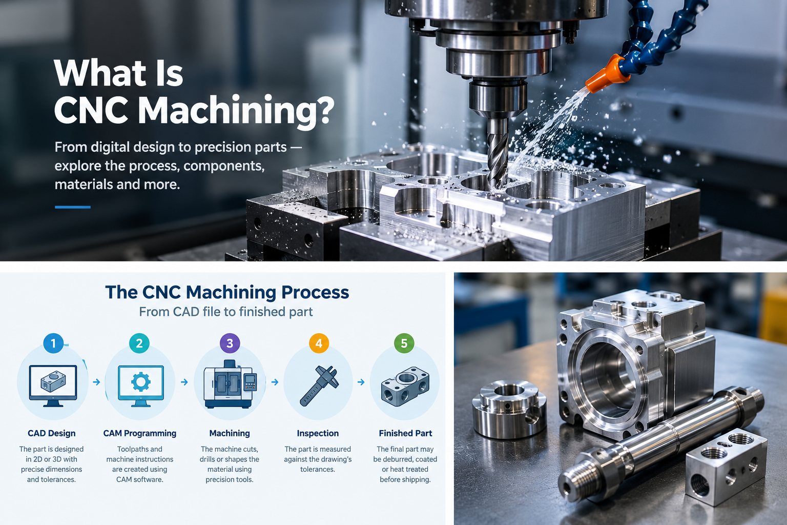
CNC machining is a subtractive process; you start with more material than the finished part needs and cut away everything that isn't the part. A block of aluminum goes into the machine; a bracket, housing, or shaft comes out, with the leftover material collected as chips. That's different from additive processes like 3D printing, where material is built up layer by layer.
The reason CNC machining matters for precision components comes down to repeatability. Once a program is proven on the first part, the machine cuts the two-hundredth part the same way it cut the first, within the tolerance the machine and tooling can hold, which is what lets an OEM assemble parts from different production runs, or different suppliers, and have them fit.
How Does CNC Machining Work?
The path from an idea to a finished CNC-machined part follows a fairly consistent sequence, even though the details vary by shop and part complexity.
1. CAD design. The part starts as a 2D or 3D CAD model, with dimensions, tolerances, and surface-finish requirements called out on the drawing.
2. Design and manufacturability review. Before anything gets programmed, the drawing gets checked against what's actually machinable. A design-for-manufacturability (DFM) review catches features that would be difficult, slow, or impossible to cut as drawn, a deep, narrow pocket with a tiny corner radius, for example, and this is far cheaper to catch here than once the part is on the machine.
3. CAM programming and toolpath generation. The CAD geometry gets converted into machine instructions using CAM (computer-aided manufacturing) software, commonly Mastercam. A programmer selects cutting tools, sets speeds and feeds for the material, and the software calculates the exact path each tool will travel through each feature.
4. Machine setup and material preparation. The right machine gets selected, a mill for prismatic geometry, a lathe for cylindrical parts, or a machine with more axes for complex, multi-sided features. Raw stock is cut to size and secured in a workholding fixture that holds it steady through every cutting operation.
5. Cutting, inspection, and finishing. The machine executes the program, removing material through operations like milling, turning, drilling, or tapping until the part matches the CAD model. The finished part is then measured against the drawing's tolerances using appropriate calibrated inspection equipment, depending on the precision required, and may go through deburring, anodizing, plating, or heat treatment before it ships, usually with documentation confirming the critical dimensions passed.
Main Components of a CNC Machine
Understanding what's actually inside a CNC machine helps explain why certain features are easy to produce and others are expensive or impossible.
Controller. The computer brain of the machine; it reads the program and translates it into precise motor commands that move the axes and control spindle speed.
Machine bed and frame. The structural base the machine is built on. A rigid frame resists vibration during cutting, which is one of the biggest enemies of a good surface finish and a tight tolerance.
Spindle. The rotating component that holds and drives the cutting tool (on a mill) or the workpiece (on a lathe), with speed matched to the material and tool for clean cutting.
Drive motors and axes. Motors move each axis with fine positional control, typically through ball screws. A basic mill has three linear axes (X, Y, Z); adding rotary axes lets the machine approach the part from additional angles without repositioning it manually.
Tool holder and workholding. The tool holder secures the cutting tool in the spindle, while vises, chucks, or fixtures hold the raw material rigidly in place; a poor workholding setup will let the part shift under cutting force, ruining tolerances even with a perfectly good program.
Cutting tools. The physical edges doing the material removal: end mills for milling, turning inserts for lathes, drills, taps, and reamers for specific features.
Feedback systems and coolant. Encoders report each axis's actual position back to the controller for real-time correction, while a coolant system controls heat, extends tool life, and clears chips from the cutting zone.
Types of CNC Machining
CNC Milling
Milling uses a rotating cutting tool to remove material from a stationary (or indexed) workpiece, making it well suited to prismatic parts, brackets, housings, plates, blocks with flat faces, pockets, and holes. A 3-axis mill moves the tool along X, Y, and Z and handles a large share of everyday parts efficiently. A 4-axis mill adds a rotary axis so features on multiple sides can be cut without manually repositioning the part. A true 5-axis mill adds a second rotary axis and can approach the part from nearly any angle in a single setup, the standard choice for complex geometries like impellers and aerospace components where stacking tolerances across multiple setups isn't acceptable.
CNC Turning
Turning is essentially the reverse of milling: the workpiece rotates in the spindle while a stationary cutting tool removes material to shape it, making it the natural fit for cylindrical parts, shafts, bushings, and fittings. Many modern lathes add live tooling, letting a rotating tool perform cross-drilling or milling without moving the part to a separate machine, cutting down on setups and the tolerance stack-up that comes with them.
4-Axis and 5-Axis Machining
Beyond the basic 3-axis setup, additional rotary axes reduce how many times a part needs to be unclamped and repositioned. Every repositioning introduces a small amount of potential misalignment, so machining more features in a single setup generally means tighter overall tolerances and fewer opportunities for error.
CNC Hobbing
Hobbing is a specialized gear-cutting process that uses a rotating, gear-shaped cutting tool (a hob) to progressively cut teeth into a rotating workpiece. It's a standard method for producing gears and splines to a specific module and tooth count, typically run on dedicated equipment rather than a general-purpose mill or lathe.
Some CNC-supported processes fall outside milling and turning entirely. CNC water jet cutting uses a high-pressure stream to cut sheet-stock profiles, useful for heat-sensitive materials, while CNC plasma cutting handles thicker plate; both typically serve as upstream steps feeding into further machining or finishing.
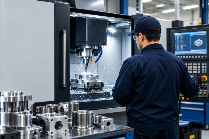
Common CNC Machining Operations
A single part might involve several of these before it's finished:
- Drilling/boring: drilling creates round holes; boring enlarges and refines an existing hole to a tighter tolerance.
- Milling/turning: milling removes material with a rotating cutter to shape flat surfaces, pockets, or contours; turning shapes a rotating workpiece against a stationary tool.
- Threading/tapping: threading cuts helical grooves for a fastener; tapping cuts those threads into a pre-drilled hole.
- Reaming: finishes a drilled hole to a precise diameter and smooth finish.
- Facing/parting: facing cuts a flat surface perpendicular to the rotation axis, often a first turning step; parting cuts the finished part off the remaining bar stock.
- Grooving/counterboring: grooving cuts a narrow recess for seals or rings; counterboring cuts a recess so a bolt head sits flush.
- Knurling: presses a textured grip pattern into a surface.
- Pocketing/profiling: removing material to create a recessed cavity, or shaping an outer or inner contour.
- Slotting/engraving: cutting a narrow channel, or shallow markings for part numbers.
Materials Used in CNC Machining
Material choice depends on the balance of strength, corrosion resistance, weight, temperature tolerance, wear resistance, machinability, and cost that the application demands.
Carbon, alloy, and tool steels cover a wide strength and cost range. Carbon steels like 1045 or 12L14 can be used for general-purpose components, while alloy steels like 4140 and 4340 are suited to structural or high-load parts. Tool steels are useful where wear resistance matters most.
Stainless steel grades like 304 and 316 are commonly selected where corrosion resistance is required, including food-processing equipment, medical components, and corrosion-exposed applications. Martensitic grades like 420 and 17-4PH (630) are heat-treatable and useful where strength and moderate corrosion resistance are both needed.
Aluminum, particularly 6061-T6 and 7075, is a workhorse thanks to its strength-to-weight ratio and machinability, common anywhere weight matters, and it anodizes well for added surface protection.
Brass, bronze, and copper each bring specific properties: brass machines cleanly for fittings, bronze offers good bearing and wear characteristics, and copper's conductivity makes it the choice for electrical components.
Engineering plastics range from general-purpose ABS, POM/Acetal, and Nylon to high-performance PEEK and PTFE for heat or chemical exposure. Worth knowing: plastic parts generally can't hold tolerances as tight as an equivalent metal part.
CNC Machining Tolerances and Surface Finishes
A tolerance is the acceptable range of variation a dimension can fall within and still be considered good. A hole might be called out as 10 mm plus or minus 0.05 mm rather than an exact 10 mm. Tolerances matter because parts rarely function in isolation; a shaft has to fit a bearing, and two mating components manufactured at different times still need to assemble correctly.
Standard tolerances, often referenced against a standard like ISO 2768, are adequate for most general features: mounting holes, non-critical surfaces, and overall envelope dimensions. Tighter tolerances get reserved for features that actually need them: a bearing bore, a sealing surface, or a mating interface. Asking for a tight tolerance where it isn't needed just adds cost and cycle time without adding value.
OELUS lists ISO 2768 medium for general features and ISO 2768 fine where required. For specific tight features, tolerances down to ±0.005 mm are available on request, depending on the part and manufacturing requirements.
Surface finish is a related but distinct specification, describing how smooth or rough a machined surface is, typically measured as Ra (roughness average) in micrometers. As-machined surfaces are usually adequate for structural features. Finer finishes from slower feed rates, additional passes, or secondary processes like polishing matter where a surface seals against something, slides against another part, or needs to look good in a visible application. The tighter the tolerance or finer the finish a feature requires, the more it costs to achieve, which is why a good drawing calls out tight tolerances only where the function demands them.
OELUS lists typical as-machined surface finishes of Ra 1.6 to 3.2 micrometers, with fine machining capable of Ra 0.4 to 0.8 micrometers. Polishing, lapping, and vibratory deburring are also available when required.
CNC Machining Process: From CAD to Finished Part
For an OEM sourcing production parts, the workflow above condenses into four practical stages: CAD validation, where engineers review a submitted drawing for manufacturability before a quote is issued; programming, where the validated CAD becomes machine toolpaths; production, with first-article inspection confirming the initial part meets spec before the full run proceeds and any post-processing happening in the same workflow; and QC and shipment, typically accompanied by a documented inspection report. Catching a manufacturability issue at the first stage is far cheaper than discovering it mid-production.
CNC Machining Applications and Industries
CNC machining shows up wherever a component needs precise dimensions and has to perform under real mechanical, thermal, or chemical conditions. In aerospace and aviation, it produces lightweight aluminum and titanium components with tight tolerances and material traceability. Automotive relies on it for engine parts, transmission components, and fluid-system fittings in series production. Medical devices depend on it for surgical instruments and implant components, frequently in 316L stainless or PEEK, where surface finish and material selection matter. In electronics, it produces enclosures, heatsinks, and connector hardware from anodized aluminum or machined brass and copper. And across industrial equipment and hydraulic systems, it's a standard way to produce housings, manifolds, and fittings that have to hold pressure and seal reliably.
Advantages of CNC Machining
The core advantage is repeatability: a proven program cuts the same part the same way, run after run, which is what makes assembly and interchangeability possible at scale. Beyond that, CNC machining offers genuine precision, the ability to produce complex geometries on multi-axis equipment, and flexibility across a wide range of metals and plastics without a different process for each. It scales naturally from a single prototype to a full production run, requires minimal manual intervention once a program is proven, and can achieve good surface finishes without secondary processing. Because it works with real engineering materials, CNC-machined parts can go straight into functional, load-bearing, end-use applications.
Limitations of CNC Machining
It's not the right fit for every project. Programming and setup take real time and expertise, which can make it less economical for a single one-off part than simpler methods. Being subtractive, it generates material waste; the chips cut away from raw stock don't become part of the finished component, and that factors into cost, along with machine time and tooling, particularly at low volumes. Certain geometries are difficult or uneconomical regardless of the machine: deep internal cavities, for instance, or features a cutting tool can't reach without more axes or a specialized setup. And tighter tolerances, while achievable, add cost and complexity, requiring additional machining control and more rigorous inspection.
CNC Machining vs. 3D Printing
The two processes solve different problems. Accuracy and tolerance generally favor CNC machining, which can hold tighter tolerances than many 3D printing processes achieve directly. Materials are broader and more predictable in CNC machining, working with standard metals and engineering plastics rather than process-specific print materials. On strength, machined parts cut from solid stock can offer predictable mechanical properties, while printed parts can have direction-dependent strength depending on the printing process and layer orientation. Surface finish out of a CNC machine is usually smoother than an as-printed surface, though both can be improved with post-processing. Where 3D printing pulls ahead is design freedom for complex internal geometries, rapid iteration on early concepts, and cost on very short-run, low-complexity prototypes.
In practice, the two processes are often complementary. It's common to prototype with 3D printing to validate form and fit quickly, then move to CNC machining once the part is ready for functional testing or production, where real material properties and tighter tolerances start to matter.
When Should You Choose CNC Machining?
CNC machining tends to be the right call when tight tolerances aren't optional, when the part needs to perform mechanically rather than just look right, and when it has to be made from an engineering material such as heat-treated steel, aluminum, or stainless steel selected for the application's requirements rather than a print-specific substitute. It's also the better choice when surface finish, precise fits, or machined threads matter, or when the component will see meaningful load, fatigue, or fluid pressure in service. And it's the natural next step once a project moves from prototype validation toward production volume, since the same process and fixturing can often scale from a handful of parts to a full run.
How to Choose a CNC Machining Partner
Once you've decided CNC machining is the right process, the harder question is who should run the job. Worth checking before committing a program to a supplier: what machine types and axis capabilities they operate, their experience across the materials your part requires, and whether their quality system matches what your application demands. Production capacity and prototyping capability matter to a shop that can take a design from first article through full production on the same equipment; this avoids the friction of re-qualifying a part with a different supplier partway through. Post-processing capability, realistic lead times, and clear communication round out the list. These considerations are covered in more depth in our guide to choosing the right manufacturing partner for OEMs.
CNC-machined components also show up constantly inside larger systems, hydraulic cylinders being a good example, where precisely machined rods, pistons, and end caps determine how well the assembly seals and performs under pressure. If that's part of what you're specifying, our guide to selecting the right hydraulic cylinder for your application covers those considerations directly.
If you're at the point of turning a design into a physical part, the next step is usually simple: send over a CAD file along with the material, tolerance requirements, surface finish, and quantity you're targeting. A manufacturability review can then flag anything worth adjusting before production starts, and you'll have a clearer picture of cost and lead time whether you're validating a prototype or scaling toward production volume.
Frequently Asked Questions
What is CNC machining in simple terms?
A manufacturing process where a computer-controlled machine cuts material away from a solid block or bar, following a digital program, to produce a precisely shaped part.
How does CNC machining work?
A CAD design is converted into toolpaths through CAM software, which the machine follows to cut, drill, or shape the material, with the finished part inspected against the original drawing.
What are the main types of CNC machining?
Primarily CNC milling (a rotating tool on a stationary part) and CNC turning (a rotating part against a stationary tool), plus multi-axis machining for complex geometries and hobbing for gears and splines.
What materials can be CNC machined?
Most commercially available metals and engineering plastics, including carbon and alloy steels, stainless steel, aluminum, brass, bronze, copper, and plastics like ABS, POM/Acetal, Nylon, and PEEK.
What is the difference between CNC milling and CNC turning?
Milling suits prismatic parts like brackets and housings; turning suits cylindrical parts like shafts and bushings, rotating the workpiece against a stationary tool.
How accurate is CNC machining?
Accuracy depends on the machine, material, part geometry, feature, and manufacturing requirements. OELUS lists standard tolerances based on ISO 2768 and states that tight features can be held to ±0.005 mm on request.
Is CNC machining suitable for prototypes and production?
Yes. The same process, programming, and often the same fixturing can take a part from a single prototype through to full production volume.